Conductor Power Systems

Conductor Power Systems — photo 1

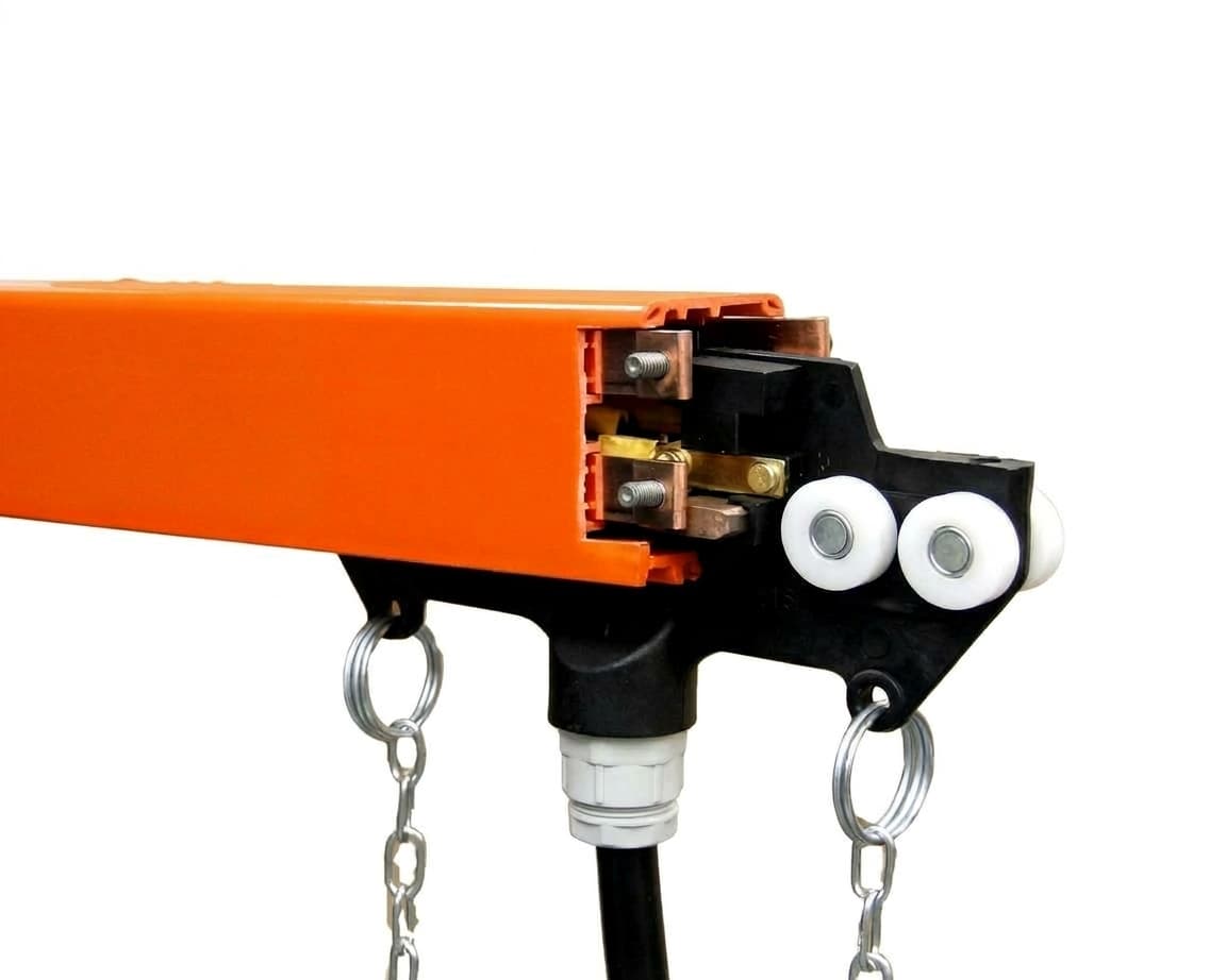
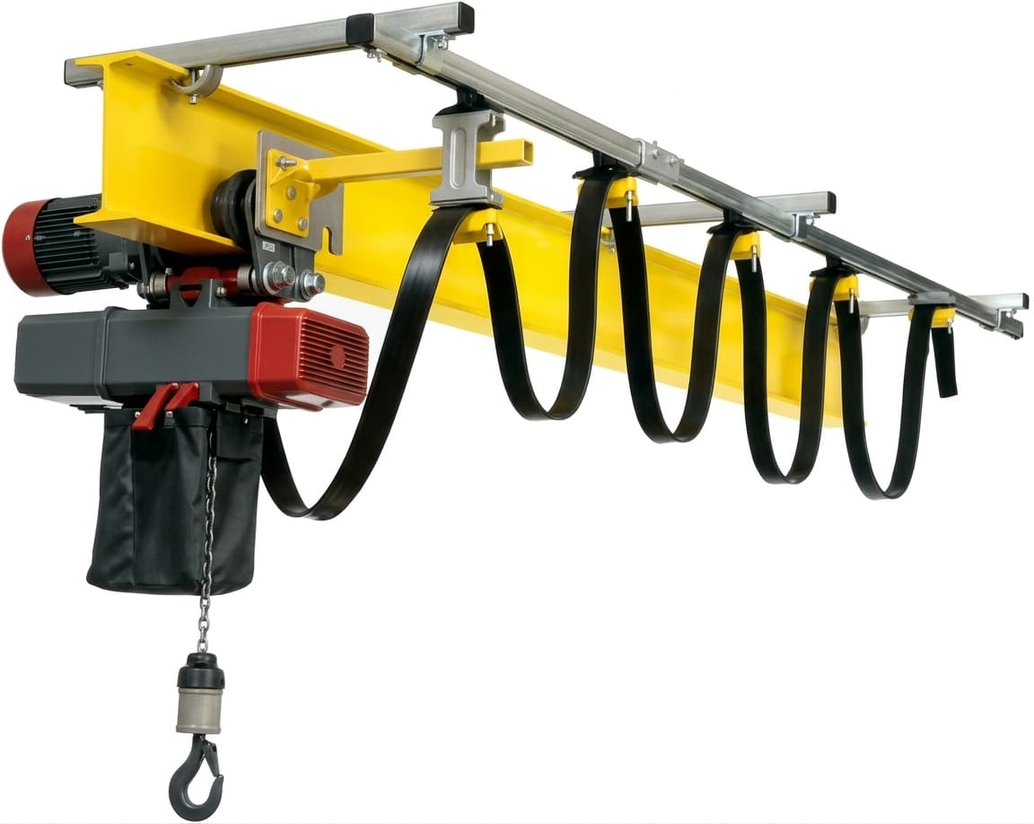
A conductor power system delivers power and control signals to equipment that moves along a track, such as a crane bridge, a hoist travelling on the bridge or a gantry crane. Since a fixed cable cannot be connected to equipment travelling tens of metres, one of three systems is used, depending on the type of movement and the environment. Enclosed conductor bars Copper or aluminium conductors sit inside an insulated PVC housing, and a current collector attached to the crane runs inside it, keeping continuous contact through spring-loaded carbon brushes. The system is used mainly to supply the long travel of an overhead crane along the hall, takes up little space, and can be extended by joining additional sections. Bendable profiles are available, so it also suits curved monorail tracks. The carbon brushes wear over time and are replaced as part of maintenance. Festoon systems Flat cables hang from trolleys running inside a C-track. As the hoist moves away the cables extend, and as it moves back they fold into loops. The system is used mainly to supply the hoist travelling across the bridge, withstands dust, moisture and outdoor use, and also suits environments where sparks must be avoided. It suits straight-line travel, and space must be left at the end of the track for the folded cables. Cable reels A round cable winds onto a drum and pays out as the equipment moves away from the feed point. The reel is spring or motor driven. It is used mainly on outdoor gantry cranes, floor transfer carts and lifting magnets suspended from the hook. Selection data Before selecting a system, determine the total current needed to run all the crane motors together under full load, the number of poles (usually three phases plus earth, sometimes with extra poles for control), and the track length. On long tracks the voltage drop should be calculated, to make sure the motors at the far end receive the correct voltage.

When to choose this

  • Continuous, reliable power supply
  • Modular construction for flexible installation
  • Protected against dust and moisture
  • Compatible with all crane types

Series and models

Choose a series for details and a quote.
Filter series

Environment

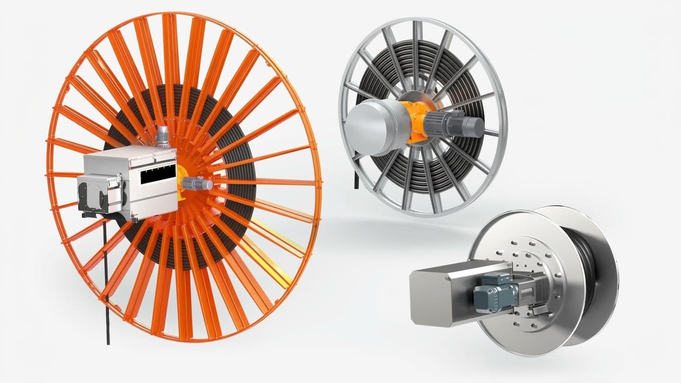
Industrial Cable Reel System

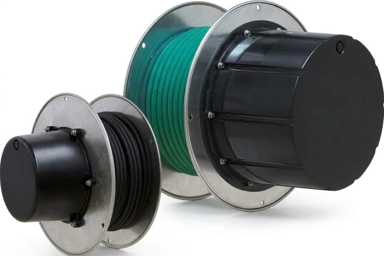
An industrial cable reel winds and unwinds a flexible power or control cable on a rotating drum, providing a continuous electrical connection to equipment travelling back and forth, such as gantry cranes, transfer carts, hoists and lifting magnets. Unlike conductor bars or festoon systems, a reel needs no track along the route, and the cable pays out in a single line behind or below the equipment. Power passes from the rotating cable to the equipment through slip rings inside the reel. Spring-driven cable reel An internal spring tensions as the equipment moves away and pays out the cable, and as the equipment returns the spring winds the cable back onto the drum. The reel works without an external power source and suits short to medium travel, relatively light cables, production lines and hook-mounted attachments such as lifting magnets. Spring tension increases as more cable is paid out, so on long runs the load on the cable increases. Motorised cable reel An electric motor with torque control or an inverter drives the drum in step with the equipment's travel speed, winding and paying out the cable without dragging it on the ground or overstretching it. It suits long travel, heavy cables and work in open yards, mining sites and large gantry cranes. When to choose a cable reel The cable is sealed and insulated along its full length, so the reel suits outdoor work in rain, dust and mud. The working area stays clear of tracks and hanging cables. Maintenance consists mainly of checking the cable sheath, the spring and the slip rings. Reels suit straight-line travel only; for tracks with curves, conductor bars are a better fit. The reel is mounted on the travelling equipment or at a fixed point beside the track. Selection depends on the travel length, the cable weight and cross-section, and the equipment's travel speed and acceleration. The model table lists the drive type, cable capacity and number of slip rings for each model.

View series

Motor Driven Cable Reel

A motor driven cable reel supplies power, control signals or fibre optics to heavy equipment travelling along long routes. An electric motor drives the drum in step with the equipment's travel speed, so the cable winds and pays out under constant tension, without overstretching or dragging on the ground. Unlike a spring-driven reel, which is limited in cable length and weight, a motor driven reel suits long travel and heavy cables. Applications Gantry cranes in open yards, ports and steel stockyards, travelling on rails over long distances. Motorised transfer carts moving moulds, castings and raw materials between halls. Cranes with lifting magnets or electric grabs, where the reel supplies the hook-mounted attachment. Mobile equipment at mines and quarries. Drive methods Torque motor: a motor that can run under load even when the shaft stalls, providing constant winding force. Suited to medium and long travel with straightforward requirements. Inverter drive: the reel controller receives data from the crane's travel system and adjusts torque to speed and acceleration at every moment, reducing load on the cable and extending its life. Magnetic coupling: the motor runs at constant speed, and power passes to the drum through a magnetic coupling that allows slip. Simple construction with little maintenance. System components Drum: on a monospiral drum the cable winds turn over turn in a single plane, and on a wide cylindrical drum the cable winds in several layers across the drum width. Slip rings: carry power from the rotating drum to the fixed electrical panel without twisting the wires. Cable guides: arms with rollers that guide the cable onto the drum during winding and keep it on track. Selection data Selection depends on the travel length, the cable type, number of cores and cross-section, and the position of the fixed feed point, at the end of the track or in the centre. The model table lists the drive type, cable capacity and number of slip rings for each model.

View series
LM-4

modular conductor rail system

  • Indoor
  • Outdoor

A modular conductor rail system supplies power to overhead cranes, monorail tracks and material handling systems travelling along a track. It is built from fixed-length profile sections that join together to match the runway length, with no exposed conductors or trailing cables. System components Conductor profiles: sections of insulated PVC housing with copper or galvanised steel conductors pre-installed inside. Joint connectors: mechanical connectors that bridge the conductors from one section to the next and keep a continuous surface, so the collector passes between sections without snagging. Current collector: a trolley attached to the crane that runs inside the profile, with spring-loaded carbon brushes keeping continuous contact with the conductors. Feed boxes: connection points to the main electrical panel, at the end or in the middle of the track. Benefits of the modular design The conductors are enclosed in an insulated housing, so live parts cannot be touched from outside. When the hall or crane runway is extended, sections are added to the existing system instead of replacing it. Profiles can be bent at the factory or on site to follow curved monorail tracks. Hangers, connectors and covers clip and bolt together, so installation needs few tools. Copper or galvanised steel Galvanised steel conductors cost less and suit low to medium currents, such as light workstation cranes, hoists and short tracks. Copper conductors suit high currents, heavy cranes and long tracks, because the voltage drop along them is lower. The model table lists the current rating, number of poles and conductor material for each model.

View series
2331

festoon cable system

  • Indoor
  • Outdoor

A festoon cable system supplies power and control to the hoist travelling across an overhead crane bridge, as well as to straight monorail tracks and short material handling runs. Flat cables hang from small trolleys running inside a C-shaped steel track. As the hoist moves away the trolleys spread out and the cable extends, and as it moves back the trolleys close up and the cable folds into loops, like a curtain. System components C-track: a galvanised steel or stainless steel track fitted along the bridge girder, with the cable trolleys running inside it. Cable trolleys: four-wheel trolleys with a curved saddle that keeps the cable within its bending radius. Towing trolley: the first trolley in the line, connected to the hoist by a towing arm and pulling the other trolleys behind it. End clamp: a fixed anchor point at the end of the track, next to the crane's electrical panel. Flat cable: a cable designed for repeated movement. The flat shape lets it fold evenly and reduces twisting and internal wear compared with a round cable. When to choose it The cable gives a continuous, insulated electrical connection with no carbon brushes to wear or collect dust and dirt, so the system suits dusty and humid environments and outdoor use. With no sliding electrical contact it does not produce sparks, and also suits explosion-hazard areas when fitted with components rated for them. Power cables for the motors and shielded control cables can run on the same track. Maintenance consists mainly of periodic checks of the cable sheathing and wheels. Design consideration When the hoist reaches the end of the bridge, all the trolleys and folded cables gather at the end of the track and take up space there. This needs to be allowed for in the design, so the hook can still get close enough to the building wall. The model table lists the track size, trolley types and cable widths for each model.

View series

Technical specification

Technical specification: Conductor Power Systems
ItemValue
זרם מרביעד 630A
מתח220 – 1000V
הגנהIP23 – IP55
חומר מוליךנחושת / אלומיניום
אורך מודולרי3 – 6 מטר ליחידה

Standards

  • EN 60204
  • IEC 60529
Download the catalogue (PDF)

Other categories

EOT Cranes (Electric Overhead Travelling Cranes)

An overhead travelling crane is installed at the top of the building and travels along a fixed runway, covering the whole hall while leaving the floor clear. The bridge travels the length of the hall, the hoist travels across the bridge and the hook raises and lowers, so the load can reach any point under the crane. Overhead cranes are used in manufacturing plants, warehouses, workshops and maintenance halls. Overhead cranes differ in two main ways: Runway mounting Top running crane: the bridge travels on rails mounted on top of the runway beams, which are supported on the building columns or on concrete corbels. This configuration suits heavy loads and wide spans. Underslung crane: the bridge hangs from the roof structure and runs on the lower flange of the runway beams. This configuration suits buildings with no room for columns, and lets the hook get closer to the side walls. Number of girders Single girder: one girder with the hoist running on its lower flange. Lighter construction and quicker to install, suited to light and medium loads. Double girder: two parallel girders with a hoist trolley running on top of them. The hook rises up between the girders, giving more lifting height, and the structure suits heavy loads and intensive duty. The right crane depends on lifting capacity, hall width, available headroom and the existing structure. The model pages list the technical data for each type. The crane moves along three axes, down the length of the building, across the bridge and vertically, and covers the entire floor area without forklifts and without temporary rigging. The first decision is the mounting method. A top running crane travels on rails carried by columns and uses almost the full height of the building, which suits heavy loads and wide spans. An underslung crane hangs from the roof structure, and suits cases where columns cannot be added or where the production floor has to stay clear, at the cost of a shorter span. The second decision is the number of girders. A single girder is lighter, less expensive and puts less load into the structure. A double girder carries far heavier loads and also gives more hook height in the same building, because the hook rises between the girders rather than below them. The third decision is the operating environment. A bridge crane is built around its hoist unit and electrical system, so it can be specified for the environment it will work in. Alongside the standard industrial build we supply versions for ATEX classified areas, for marine and coastal installations, for dusty and high humidity conditions and for aggressive chemical environments. The specification is fixed at the design stage rather than retrofitted, so the environment should be defined in your first enquiry. We supply 129 configurations across three series: single girder from 2 to 12.5 tonnes over spans of 10.5 to 31.5 metres, double girder from 5 to 50 tonnes over spans of 13.5 to 31.5 metres, and underslung from 2 to 10 tonnes over spans of 6 to 20 metres. Standard lifting height is 9 metres and the duty rating is A5 to FEM 2M. Every crane is engineered to your building dimensions, your loads and your operating environment rather than selected from a catalogue. We carry out the site survey, the design, the installation and the commissioning, and stay with the crane through routine maintenance for its working life.

See details

Need a quote for this?

Tell us what you need and we will come back with a specification and a price.

Request a quote
Call us nowChat with us on WhatsApp