Pulling Winch

Pulling Winch — photo 1

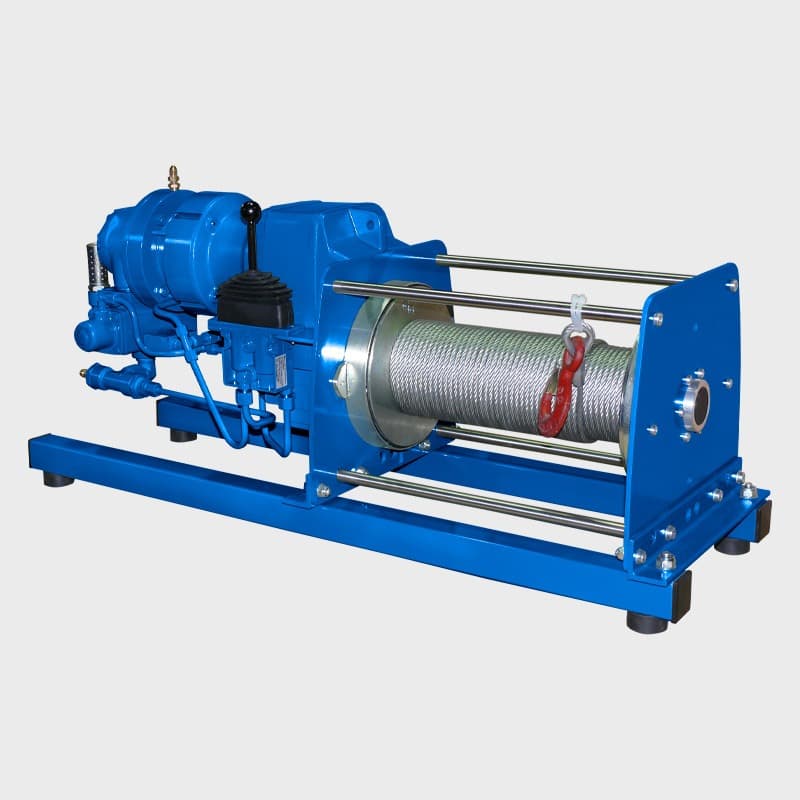
A pulling winch hauls or tensions a load horizontally or up an incline, using a steel wire rope or synthetic rope wound on a drum. It is used to haul carts and loads along a track in a plant, pull equipment up ramps, pull cables through ducts and conduits, and tension cables and loads. A pulling winch is not a lifting winch. Lifting winches are designed with a braking system and safety factors suited to a suspended load, whereas a pulling winch is intended for loads that are dragged or rolled. A pulling winch must not be used to lift a load vertically. Types of pulling winch Industrial electric pulling winches: winches with a steel frame anchored to the floor or a structure, with a large cable capacity drum, for repeated horizontal hauling of carts and loads along a fixed route. Cable pulling winches: electric winches for continuous work, usually with two speeds and foot pedal control, leaving the operator's hands free to guide the cable. Intended for electrical, infrastructure and telecom contractors pulling cables through ducts, tunnels and underground conduits. Manual winches and pulling machines: hand-cranked geared winches, and pulling machines where the wire rope passes through the unit instead of winding on a drum, so pulling length depends only on rope length. Suited to sites with no power supply. Selection data The pulling force needed depends on how the load moves: a load on wheels needs far less force than one dragged along the ground, and an incline increases the force required. Steel wire rope resists wear and abrasion better but is heavier and more dangerous if it breaks. Synthetic rope is lighter and less dangerous on breaking, but more sensitive to heat and abrasion. Also check that the drum capacity matches the pulling distance and that the available power supply suits the winch. The model table lists the pulling force, cable capacity, pulling speed and operating voltage for each model. We supply pulling winches in three drive types, from 1.2 to 37 tonnes. The electric version runs an IP54 braked motor rated 2.2 to 45 kW. The pneumatic version works at 7 bar with an air consumption of 90 to 350 litres per second, which suits areas where electricity is not permitted. The hydraulic version is the fastest of the three at up to 35 m/min, and fits mobile equipment that already carries a hydraulic system. The drum is built to classification 1Am with a diameter at least 16 times the rope diameter, and the rope is selected for the pulling force at the fifth rope layer rather than the first. This is easy to miss: the force drops by roughly thirty percent between the first layer and the fifth, so we publish both figures for every model. The standard build ships without rope and without controls, both selected separately to suit the application. A load limiter is required under CE for any application above 1,000 kg working load limit. Explosion-proof motors and marine-duty versions are available, with paint systems to ISO 12944 grade C4 or C5-M.

Series and models

Choose a series for details and a quote.
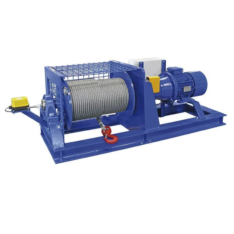
PHW-E

Electric Pulling Winch

  • 1250–37000 kg
  • Electric

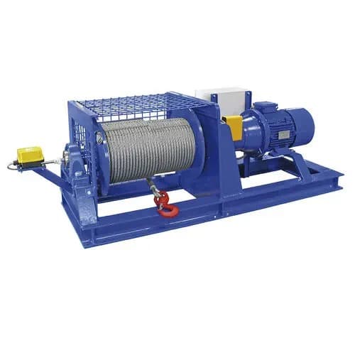
An electric pulling winch is a motorised winch for hauling, pulling and tensioning loads horizontally or up an incline. An electric motor drives a drum carrying a steel wire rope or synthetic rope, and a brake holds the load when the motor stops. The winch is intended for loads that are dragged or rolled, and must not be used to lift a load vertically, since it lacks the braking system and safety factors of a lifting winch. Types by application Fixed industrial pulling winches: winches with a steel frame anchored to the floor, used in plants, shipyards and rail depots for repeated hauling of carts and heavy loads along a fixed route. They run on three-phase power, have a large cable capacity drum and overload protection, and are designed for frequent duty cycles. Cable pulling winches: winches for electrical, infrastructure and telecom contractors pulling cables through ducts, conduits and tunnels. They run on single-phase or three-phase power, usually with several speeds, tension control and foot pedal operation that leaves the operator's hands free. Selection data Pulling force: the winch's pulling force is highest on the first layer of rope on the drum and decreases as layers build up. Calculate the required force for the layer the winch will work on. A load on wheels needs far less force than one dragged along the ground, and an incline increases the force required. Rope type: steel wire rope resists abrasion against concrete and rock, but is dangerous if it breaks. Synthetic rope is lighter and less dangerous on breaking, but sensitive to heat, friction and UV. Duty cycle: determine whether the winch will work occasionally or continuously for hours, and choose a model designed for it. Operating voltage: single-phase or three-phase, depending on what is available on site. The model table lists the pulling force, cable capacity, pulling speed and operating voltage for each model.

View series
PHW-L

Pneumatic Pulling Winch

  • 1200–20000 kg
  • Pneumatic

A pneumatic pulling winch is powered by compressed air and used to haul, pull and tension loads horizontally or up an incline. It suits environments where an electric motor is a hazard, such as explosion-risk areas or wet conditions, and continuous work over many hours. Like an electric pulling winch, it is intended for loads that are dragged or rolled, and must not be used to lift a load vertically. Why an air motor An air motor has no wiring, electronics or carbon brushes, so it does not produce sparks. The winch suits refineries, chemical plants, offshore platforms and mines, in models approved for explosive atmospheres. Air flowing through the motor cools it during operation, so the winch suits long periods of work without cooling breaks. The operator controls pulling speed progressively, from a slow creep to full speed, by how far the control lever is pressed. The motor withstands humidity, rain, salt air and dust. Motor types Radial piston motor: delivers high starting torque, suited to pulling heavy loads at relatively low speed. Vane motor: more compact and lighter, reaching higher pulling speeds. Suited to light and medium loads where a fast work rate is needed. Selection data A pneumatic winch uses a large volume of air, so check that the site's compressed air system supplies the pressure and flow the winch requires. Otherwise it will not reach its full pulling force. A filter, regulator and lubricator unit should be fitted on the air line feeding the winch to protect the motor from moisture and dirt. Also determine the required pulling force and the rope length needed for the hauling distance. The model table lists the pulling force, rope capacity, pulling speed, motor type and air consumption for each model.

View series
PHW-H

Hydraulic Pulling Winch

  • 2500–37000 kg
  • Hydraulic

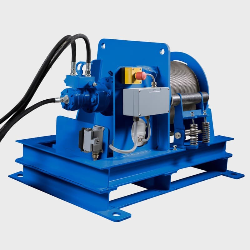
A hydraulic pulling winch is powered by oil pressure and used to haul, pull and tension heavy loads horizontally or up an incline. A hydraulic motor produces high pulling force from a relatively compact unit, so the winch suits heavy loads in shipyards, ports, on vessels, on recovery vehicles and in heavy industry. Like other pulling winches, it is intended for loads that are dragged or rolled, and must not be used to lift a load vertically unless the model is designed and approved by the manufacturer for lifting as well. Benefits of hydraulic drive The winch suits continuous work under load, as long as oil flow is maintained and the hydraulic system includes suitable cooling. There is no electrical wiring at the drum, so it suits work in rain, marine environments and wet conditions, and in models approved for them, explosive atmospheres. Regulating oil flow at the valve block changes pulling speed progressively, from a slow creep to fast hauling. Installation types Fixed winches: winches anchored to a concrete floor or steel structure in plants, ports and shipyards, for hauling rail cars, carts and boats. They are fed by a separate hydraulic power unit with an electric motor, pump and oil tank. Vehicle and vessel winches: winches mounted on recovery trucks, tow trucks and vessels, fed from the vehicle's hydraulic pump through a power take-off. They usually include a free-spool clutch for paying out the rope quickly by hand, and a brake that locks automatically when pressure drops. Selection data Operating pressure: determines the winch's pulling force. Make sure the hydraulic system does not exceed the winch's rated pressure. Oil flow: determines pulling speed. Flow below the requirement will slow the winch. Counterbalance valve: a valve in the valve block that stops the drum from overrunning when the load is on a downslope or pulling the rope by itself. Also determine the required pulling force, the rope length and the hydraulic power source: an existing power unit, a new unit or the vehicle's pump. The model table lists the pulling force, rope capacity, pulling speed, operating pressure and oil flow required for each model.

View series

Other categories

EOT Cranes (Electric Overhead Travelling Cranes)

An overhead travelling crane is installed at the top of the building and travels along a fixed runway, covering the whole hall while leaving the floor clear. The bridge travels the length of the hall, the hoist travels across the bridge and the hook raises and lowers, so the load can reach any point under the crane. Overhead cranes are used in manufacturing plants, warehouses, workshops and maintenance halls. Overhead cranes differ in two main ways: Runway mounting Top running crane: the bridge travels on rails mounted on top of the runway beams, which are supported on the building columns or on concrete corbels. This configuration suits heavy loads and wide spans. Underslung crane: the bridge hangs from the roof structure and runs on the lower flange of the runway beams. This configuration suits buildings with no room for columns, and lets the hook get closer to the side walls. Number of girders Single girder: one girder with the hoist running on its lower flange. Lighter construction and quicker to install, suited to light and medium loads. Double girder: two parallel girders with a hoist trolley running on top of them. The hook rises up between the girders, giving more lifting height, and the structure suits heavy loads and intensive duty. The right crane depends on lifting capacity, hall width, available headroom and the existing structure. The model pages list the technical data for each type. The crane moves along three axes, down the length of the building, across the bridge and vertically, and covers the entire floor area without forklifts and without temporary rigging. The first decision is the mounting method. A top running crane travels on rails carried by columns and uses almost the full height of the building, which suits heavy loads and wide spans. An underslung crane hangs from the roof structure, and suits cases where columns cannot be added or where the production floor has to stay clear, at the cost of a shorter span. The second decision is the number of girders. A single girder is lighter, less expensive and puts less load into the structure. A double girder carries far heavier loads and also gives more hook height in the same building, because the hook rises between the girders rather than below them. The third decision is the operating environment. A bridge crane is built around its hoist unit and electrical system, so it can be specified for the environment it will work in. Alongside the standard industrial build we supply versions for ATEX classified areas, for marine and coastal installations, for dusty and high humidity conditions and for aggressive chemical environments. The specification is fixed at the design stage rather than retrofitted, so the environment should be defined in your first enquiry. We supply 129 configurations across three series: single girder from 2 to 12.5 tonnes over spans of 10.5 to 31.5 metres, double girder from 5 to 50 tonnes over spans of 13.5 to 31.5 metres, and underslung from 2 to 10 tonnes over spans of 6 to 20 metres. Standard lifting height is 9 metres and the duty rating is A5 to FEM 2M. Every crane is engineered to your building dimensions, your loads and your operating environment rather than selected from a catalogue. We carry out the site survey, the design, the installation and the commissioning, and stay with the crane through routine maintenance for its working life.

See details

Need a quote for this?

Tell us what you need and we will come back with a specification and a price.

Request a quote
Call us nowChat with us on WhatsApp